Table of Contents
The Proportional Scaling Fallacy at Small Scale
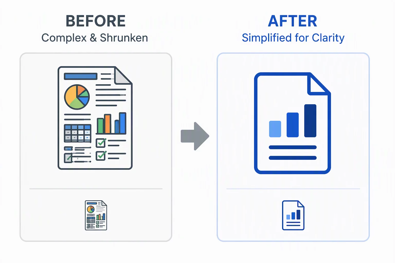
When design artwork transitions from an infinite digital artboard to a physical cutting bed, mathematical uniformity collides with physical constraints. Standard linear downscaling treats every curve and clearance gap equally, shrinking a 100 mm insignia down to 25 mm by uniform division. The digital preview still appears coherent on a high-density screen, yet the mechanical blade encounters micro-clearances that tear vinyl films, bunch up adhesive layers, and turn negative spaces into indistinguishable cut clusters.
Real-world production fidelity demands optical redesign rather than pure scaling. When an internal negative cavity drops below 0.6 mm, preserving it does not communicate intricate craftsmanship; instead, it invites weeding failure and guarantees that surface adhesion will fail under standard handling. Pruning auxiliary internal cutouts, eliminating non-essential accent contours, and merging adjacent parallel paths restores visual legibility while respecting the turning radius of fine drag blades.
Dimensional Thresholds & Cut Tolerances
| Specification Parameter | Verified Tolerance | Standard Threshold |
|---|---|---|
| Internal Cavity Clearance | ≥ 0.75 mm (Pruned) | 0.25 mm (Linear scaled / Fails weed) |
| Blade Tangent Turning Arc | Radius 0.35 mm min | Radius 0.10 mm (Path lifting hazard) |
| Isolated Island Footprint | ≥ 1.20 mm² surface area | < 0.40 mm² (Adhesive detachment) |
| Positive Stroke Thickness | 0.70 mm consolidated | 0.18 mm (Torn during transfer) |
Shrinking an intricate path preserves every mathematical node while destroying mechanical feasibility. Removing secondary geometry saves the character of the design where physical limits bite.
Strategic Pruning: What to Keep vs. Eliminate
Before sending any scaled-down design to a plotter, inspect every acute angle and secondary interior cutout under calibrated magnification. A systematic reduction workflow isolates visual anchor lines from dispensable micro-flourishes through three physical evaluation steps:
- Close internal negative openings that measure under 0.6 mm, turning porous inner areas into solid structural silhouettes that remain robust during transfer tape peeling.
- Absorb secondary drop shadows and detached outline offsets into the primary silhouette body to prevent loose thread-like vinyl slivers.
- Replace clusters of miniature texture dots or stippling with single cohesive shape forms, eliminating isolated islands smaller than 1.2 mm².
In software like Silhouette Studio, testing path integrity via a temporary outward offset of 0.2 mm immediately highlights choke points where the blade would attempt impossible micro-turns. Pruning redundant path nodes not only clean up the resulting decal but also accelerates plotter carriage movements, reducing total cutting cycle duration by nearly half.
Production Verdict & Scale Tiers
When an element requires 400% zoom on a monitor just to discern whether it is a cutout or an anchor point, that element will never survive as a 25 mm physical adhesive cut. The most effective production workflow produces three dedicated design tiers: high-fidelity for large formats above 90 mm, a balanced secondary version for medium applications, and a pruned high-contrast silhouette specifically crafted for sub-35 mm footprints.
Vector Tolerance Field Bulletins
Receive technical teardowns, node clearance benchmarks, and cut failure post-mortems straight to your inbox.
Technical Log Observations
Fieldbook Review ChannelThis could be your first comment.
Submit Observation Note