Table of Contents
The 15 mm Physical Boundary Test
Minimalist pictograms depend entirely on optical balance between positive stroke weights and negative gaps. While a 1.5 pt stroke appears light and breathable on a high-density 4K display, converting that geometry into a 15 mm vinyl cut exposes severe physical limitations. In mechanical plotters, dragging a carbide blade around micro-radii introduces lateral friction that shears delicate vector bridges right off the silicone backing paper.
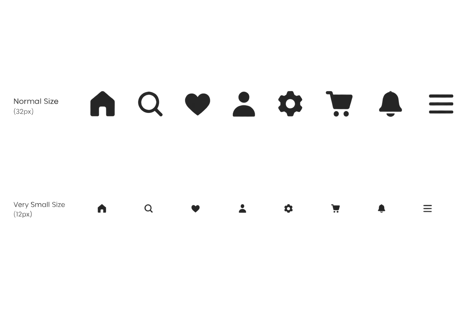
During our controlled evaluation in Silhouette Studio, we subjected a uniform set of navigation glyphs to sequential downscaling runs. The test suite encompassed arrows, search loupes, battery cells, and geo-pins across four distinct output sizes: 45 mm, 30 mm, 20 mm, and 15 mm. The primary goal was to pinpoint the exact dimensions where unexpanded strokes fail mechanical clearance or cause catastrophic weeding tears.
Calibrated Geometry Benchmarks
| Specification Parameter | Verified Tolerance | Standard Threshold |
|---|---|---|
| Minimum Stroke Width | 0.48 mm at 15 mm icon box | 0.30 mm baseline cut limit |
| Negative Counter Aperture | 0.62 mm minimum clearance | 0.40 mm peel clearance |
| Internal Corner Radius | R 0.18 mm tangent bevel | R 0.10 mm minimum blade turn |
| Weeding Island Area | 1.42 mm² retained surface | 0.75 mm² adhesion limit |
A minimalist icon never scales linearly. The internal negative apertures choke twice as fast as the exterior contour shrinks, transforming airy symbols into indistinct blocks of vinyl.
Counter-Space Choking & Blade Offset
When an icon shrinks below 20 mm, the software's native cut line sits dead center on the path. However, a physical blade has a tangible knife radius of approximately 0.25 mm. Because the blade pivots behind the carrier shaft, it cuts slightly outside the ideal internal perimeter and slightly inside external corners, eating directly into tiny negative slots.
- Internal loops in symbols such as search handles or padlocks seal shut completely unless manually expanded by a minimum 25% negative offset.
- Isolated micro dots, like those on exclamation marks or broadcast icons, drop below the critical 1.4 mm² surface adhesion threshold and lift off during plotting.
- Parallel stroke channels positioned closer than 0.60 mm trap excess adhesive, causing neighboring vinyl sections to fuse back together as the waste sheet is peeled.
To overcome these defects without destroying visual continuity, we applied optical compensation in the vector design prior to cutting. Increasing internal hole radii while trimming outer cap boundaries allowed the 15 mm glyphs to preserve the recognizable optical heft of their 45 mm parent files.
Engineering Rules for Micro Icons
Scaling minimalist iconography for physical production demands deliberate redrawing rather than mathematical downsampling. Always maintain a stroke width floor of 0.48 mm on intermediate vinyl, widen enclosed apertures beyond standard screen proportions, and convert sharp zero-radius corners to gentle 0.18 mm fillets. Following these bounds guarantees crisp cuts, reliable weedability, and instant signpost recognition even at fingertip dimensions.
Get the Icon Calibration Matrix
Detailed technical reference tables with blade offsets, stroke multipliers, and negative gap ratios for micro vinyl fabrication.
Technical Log Observations
Fieldbook Review ChannelNo comments yet. Be the first to leave a comment.
Submit Observation Note