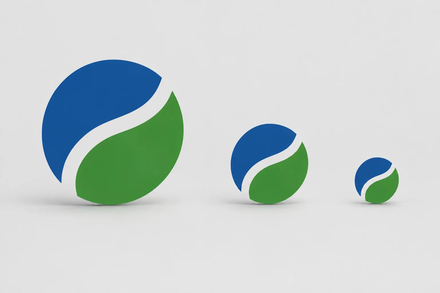
 1:1 Scale Test
Corporate Logo Scaling
Assessing path distortion, interior counter spaces, and kerning shifts when resizing core corporate emblems down to 25 mm vinyl cuts.
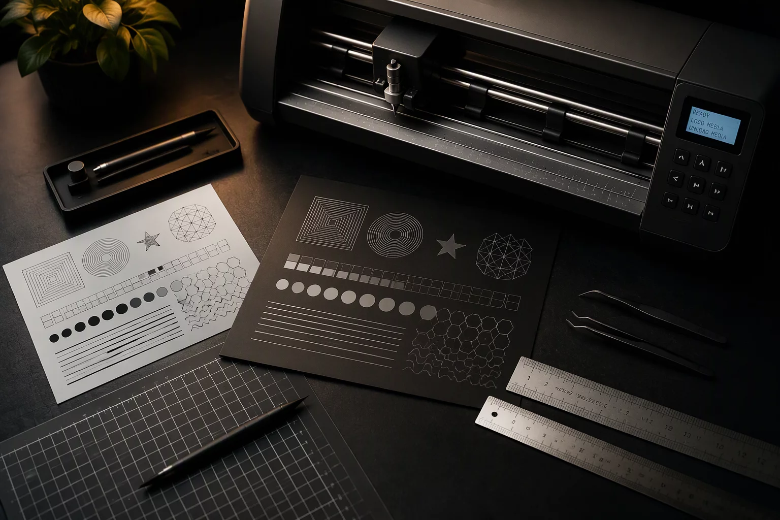
Compare the same design at different sizes and review text, spacing, internal openings, narrow features, and visual balance before cutting.
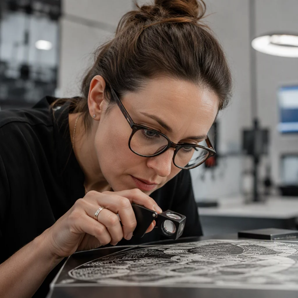
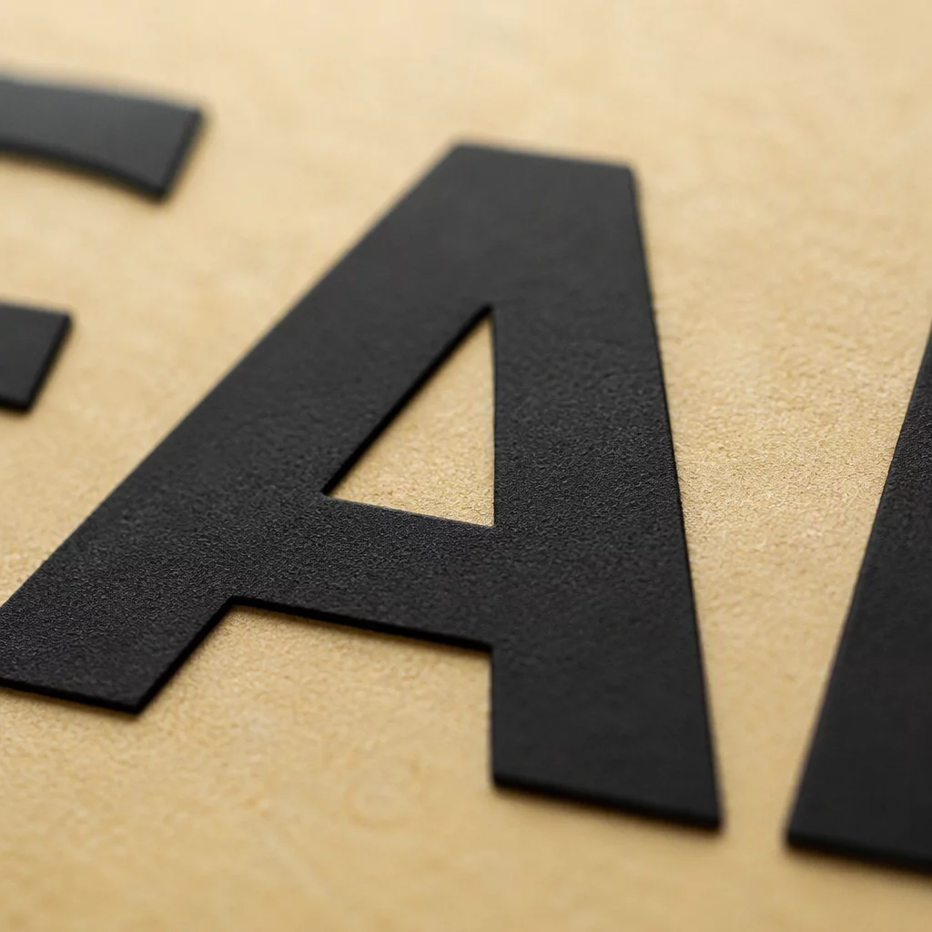
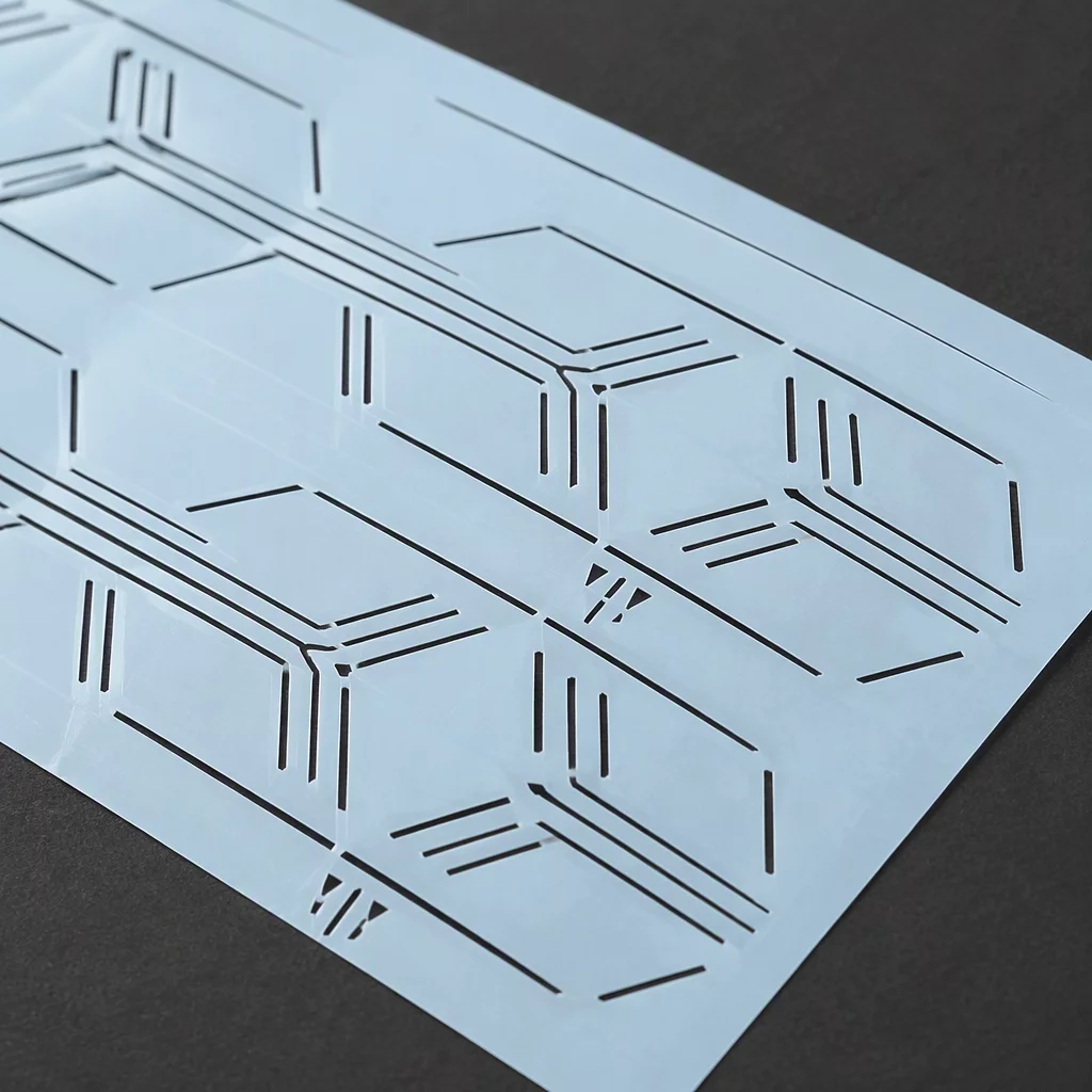
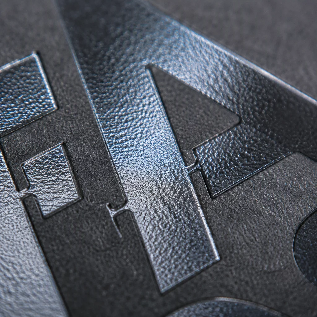
Systematic physical vector validation across eight foundational parameters. Examine how cut path tension, negative space weeding, and curve node counts respond under precise dimensional scaling.
Physical stepped cut proofs executed at 25 mm increments to map material shear limits and adhesive peel resistance before batch fabrication.
Sub-25 mm cut boundaries requiring micro-offset stroke adjustments, node reduction, and acute corner filleting to prevent vinyl lift.
Expansions exceeding 150 mm where blade drag displacement, structural thermal drift, and backing sheet deformation dictate vector grouping.
Optical kerning overrides and stem-width compensation necessary when converting letterforms into physical adhesive paths across formats.
Internal negative punch voids that collapse under high tool friction or peel off prematurely during high-velocity weeding passes.
Continuous hair-width vectors that encounter lateral blade drag, requiring path duplication, overcut compensation, and speed downshifts.
Unified vector master sets configured to output 25 mm, 60 mm, and 120 mm variations without manual path rebuilding or distortion.
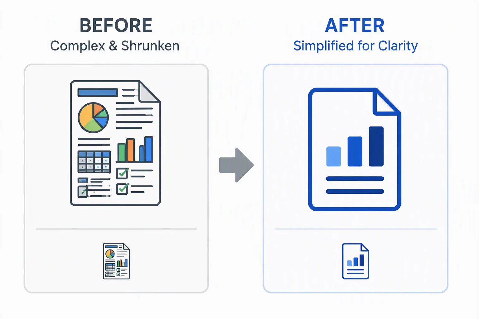
Strategic path ablation and vector pruning methods evaluated when simple linear reduction chokes blade passage or ruins visual hierarchy.
Inspect Case StudyEvery architecture module aligns with physical drag knife physics, 0.25 mm blade offset math, and cutter downforce limits to guarantee reproducible output.
Scaling a vector contour linearly does not scale physical blade physics, material adhesion, or blade travel tolerances. When downscaling by 70%, every vector element must undergo structural triage: keep, simplify, or remove.
 High Risk Scale Factor
Evaluated in Silhouette Studio 4.5. Standard 651 vinyl cut cleanly at 100 mm, but catastrophic edge lifting, blade snags, and torn counters occurred at 30 mm before vector node optimization.
The master outline preserves boundary identity. At 100 mm, node curves are fluid. At 30 mm, cut trajectory remains continuous without tight 90-degree needle turn loops, maintaining complete perimeter adhesion.
Internal cavities scaled down to 0.4 mm in width. Plotter blade snagged tiny negative scraps during weeding. Merged neighbouring cutouts and widened bridge clearances to a minimum 0.9 mm offset.
A 5 pt decorative slogan under the emblem turned into un-weedable confetti vinyl dots at 30 mm. Removed typography completely from small scale cut path and preserved solely for print files.
Tight parallel contour grooves lost material tension and lifted under transfer tape. Switched double-hairlines into a single bolded groove by collapsing redundant node paths into a 1.2 mm channel.
Twelve decorative starbursts and floating flecks detached upon carrier sheet peeling. Isolated dots lacked required surface contact area; dropped entirely to protect decal longevity.
Before cutting blades touch vinyl or vector nodes are restructured, we establish strict mathematical parameters. Reviewing deliverables in advance eliminates misaligned expectations and guarantees repeatable physical results.
Elimination of self-intersecting loops, redundant nodes, and micro-cusps below 0.35 mm threshold.
Blade offset compensation settings, acceleration ramps, and force presets for Silhouette Cameo and Curio.
Separate vector versions engineered specifically for 25 mm, 60 mm, and 120 mm physical outputs.
Widening of negative cutouts and tight letters so interior vinyl weeding remains clean and damage-free.
Converting hairline borders into self-supporting cutting contours to prevent tearing during blade turns.
A documented single-page spec sheet detailing minimum radius limits, kerf gaps, and blade speeds.
We perform one test validation cut per scale tier; mass decal fabrication remains the client responsibility.
Replacing dulled 45-degree drag blades or cleaning cutting mats on client hardware is not covered.
We optimize existing vector paths for physical scale integrity; we do not produce alternate brand concepts.
Procurement of cast vinyl rolls, transfer tapes, or specialized release liners is handled by your print shop.
Deliverables are formatted for desktop vector plotters and Silhouette Studio, not heavy milling machinery.
Physical peel-and-stick application on field vehicles, windows, or signage panels is outside our scope.
Vector geometry does not always translate cleanly to high-drag physical blades. We test every profile across production software builds and micro-stepper cutting plotters to ensure zero node drift at every scale.
Direct SVG importing, nested weeding lines, automated multi-cut offset, and fine kerf calculation down to micro-blade tolerances.
Cleaning cusp artifacts and reducing overlapping anchors before file passing. Eliminates vinyl tearing on acute corners under 30°.
5 kg downward force support with tool chamber auto-detection. Used for rigorous scaling benchmarking on cast adhesive films.
Standard 60° and 45° blade geometries calibrated to measure lift friction on sub-10mm typography and micro-decal internal cutouts.
Independent physical verification checking perimeter kerf shrinkage and blade drag distortion after substrate weed tests.
Enables direct plotting straight from vector artboards without intermediate rasterization, preserving layer-defined cut speeds and depths.
Vector curves that preview crisp on high-DPI displays frequently tear, over-cut, or fill solid at miniature physical dimensions. Click the primary issues you face to generate immediate workflow corrections, stages, and validation rules.
Calibrated adjustments formulated for the exact challenges selected above:
Direct solutions to common manufacturing concerns and misconceptions:
Step sequence for Silhouette Studio preparation and production checks:
Explore our documented field reference to inspect physical blade depth and compensation matrices.
Laboratory records analyzing vector node behavior, mechanical knife drift, and path simplify routines across diverse physical output dimensions in Silhouette Studio.
1:1 Scale TestAssessing path distortion, interior counter spaces, and kerning shifts when resizing core corporate emblems down to 25 mm vinyl cuts.
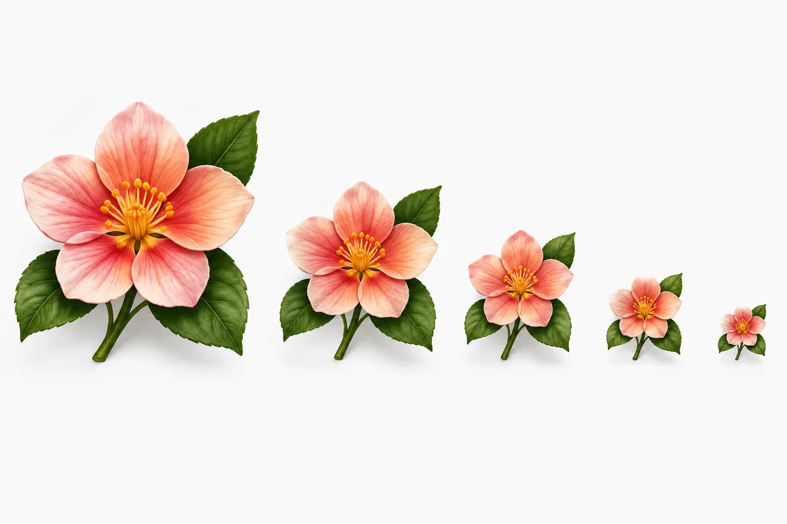 Blade Kerf Check
Evaluating micro-tears in cardstock when botanical filigree nodes drop below the threshold limit of 0.4 mm blade sweep radiuses.
 Stroke Weight Test
Analyzing optical weight balance and serif survivability across broadsheet print formats down to adhesive packaging labels.
 Node Geometry
Examining outline node retention versus unified compound paths when fabricating compact 16 mm thermal transfer icon stickers.
Practical guidelines, boundary constraints, and visual balance comparisons across physical vector reproduction sizes.
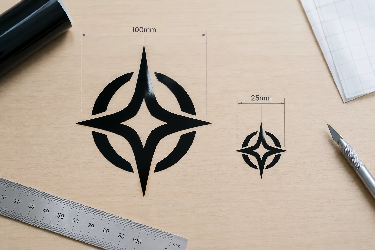
Direct dimension comparison of identical cut vectors revealing how mechanical limits collapse delicate geometry.
Read Article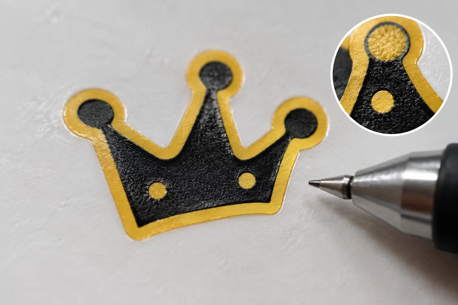
Why sub-millimeter negative counters fuse together under blade drag and require path elimination.
Read Article
Secondary typography bottlenecks entire emblem dimensions when scaled downward without optical restructuring.
Read Article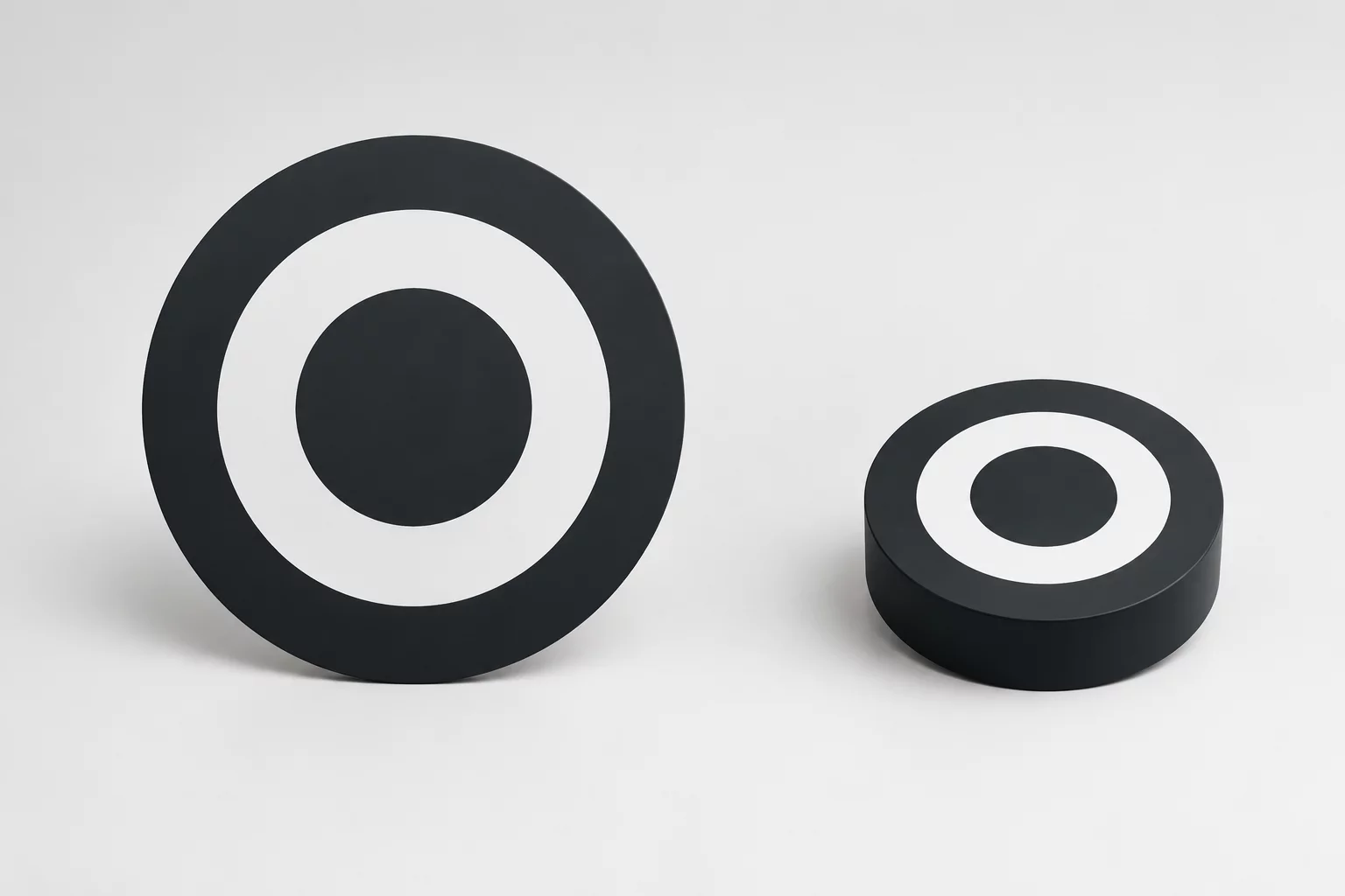
Optical compensation rules that prevent compact vector marks from appearing overly dense and heavy.
Read Article